Your cart is currently empty!
Making a Steel Rolling Mill Part 1
Part 1
In this tutorial I will go through the process of building the McDonald rolling mill as I did.
I made mine to assist me in the process of making Damascus and knife making.
The inventor and designer of this mill is Hugh McDonald from Western Australia. Hugh deserves all the credit for coming up with the idea and making it work.
I am not offering the plans here and will not be going into the dimensions in detail unless it is to point out how I have changed the method of build compared to Hugh’s plans.
The plans are available online and cost me $25 US. They are detailed and downloadable and very good value for this project. The direct link for these is www.etsy.com/shop/McDonaldRollingMill
Please do not email me and ask me to supply them. If you begrudge paying that amount then you should not make the mill. Hugh McDonald deserves what he gets from selling the plans.
Most of us would agree that when we think of steel rolling mills we think of units that weigh many tons and use a lot of horsepower. Here with Hugh’s design we have a mill that will sit on the floor of your home workshop, run off a small single phase motor and your neighbour would not even know it was running.
In speaking with Hugh about the making of the mill he said there was really no particular point at which the building had to start and it was up to the builder to decide at what point to begin. He was also clear in that there was almost no part of the mill that could not be adapted to suit the materials that were on hand.
Hugh also said in his notes that most of the materials he used were scrounged or from his scrap heap……In my case I did the same for some parts and materials and purchased whatever else necessary.
I have made this tutorial to try and assist others that wish to make the mill and show how I went about it and the changes I made in comparison to Hugh’s plans. Most of these changes were brought about by using different materials to the original and the fact that I had a milling machine. Quite handy!!!
I have used the same terminology for the components in the mill on the assumption that the builder will have Hugh’s plans and understand the meaning of those terms.
Rather than make a video I chose to make this tutorial with still images that I hope may assist people if they wish to copy them.
As stated before there is no set place to start the build. That is fine if you use the same materials as are in the plan and there are very detailed dimensions in the plans to follow.
If however your materials are different as mine were, then you need to give careful thought as to how a change in the dimension of one component will affect the size or placement of another component in the mill.
Hugh told me that he started building his mill by turning the rollers…he said he enjoyed lathe work. As I used a different size of channel (larger) in the base than specified in the plans, I decided to make the main frame first and that would then give me the dimensions for the rollers.
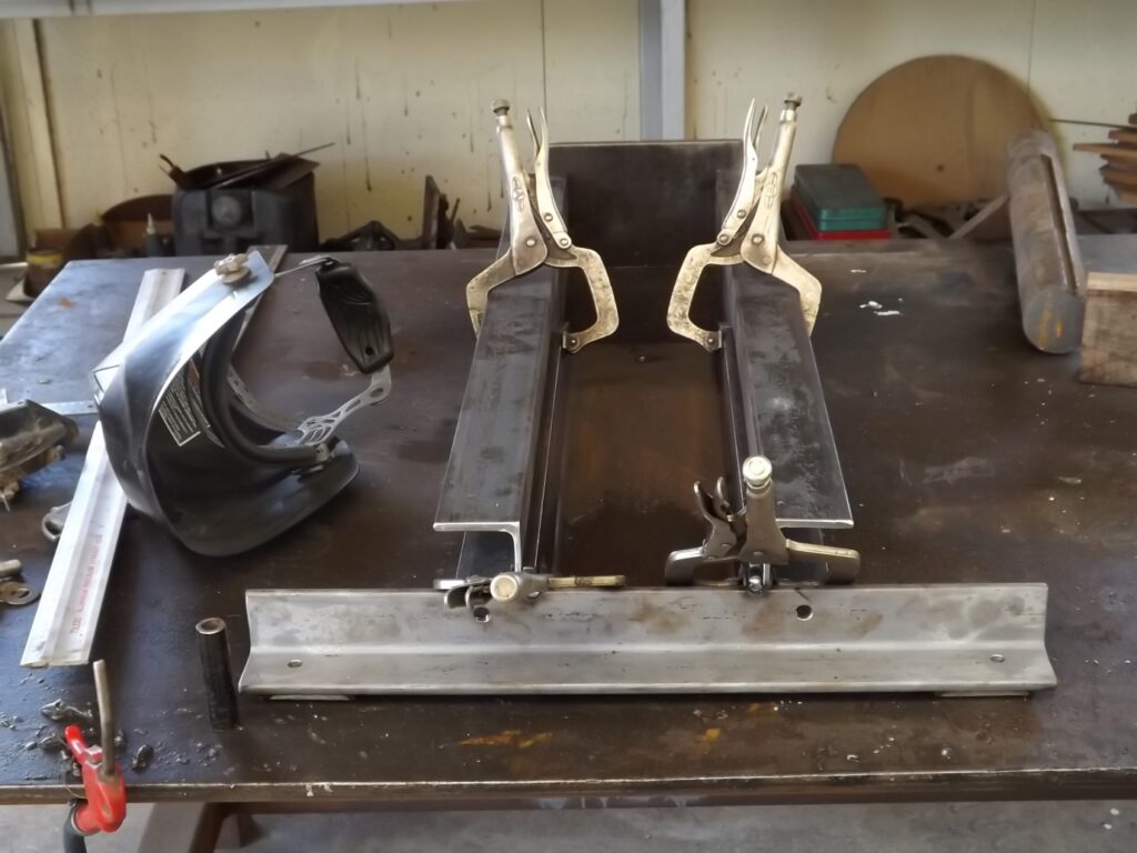
The image (1) you see here, the base has been fabricated and the main frame uprights clamped to it to give the correct spacing apart for the uprights.
(1)
I then made the top cap while the main frame uprights were clamped and fitted it.
The top cap was bolted in place rather than welded. I wanted to keep the mainframe uprights separate or should I say able to be separated so I could place them in the mill later and do further work on them.
The image (2) shows the main frame uprights in their correct position and the top cap bolted to them.
I had already drilled the holes in the base plate components and with the uprights in place could mark the hole position on them and then take them down and drill the holes
(2)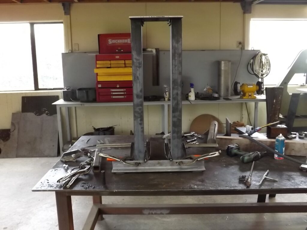
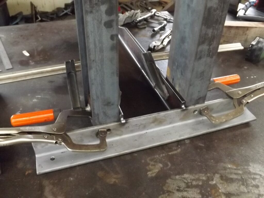
Image (3) is a closer shot of the uprights bolted to the base plate showing the drilled holes through which they can be marked on the uprights.
Because nothing is welded the uprights can be taken off and worked as individuals.
(3)
The next part I made was the bottom roller frame.
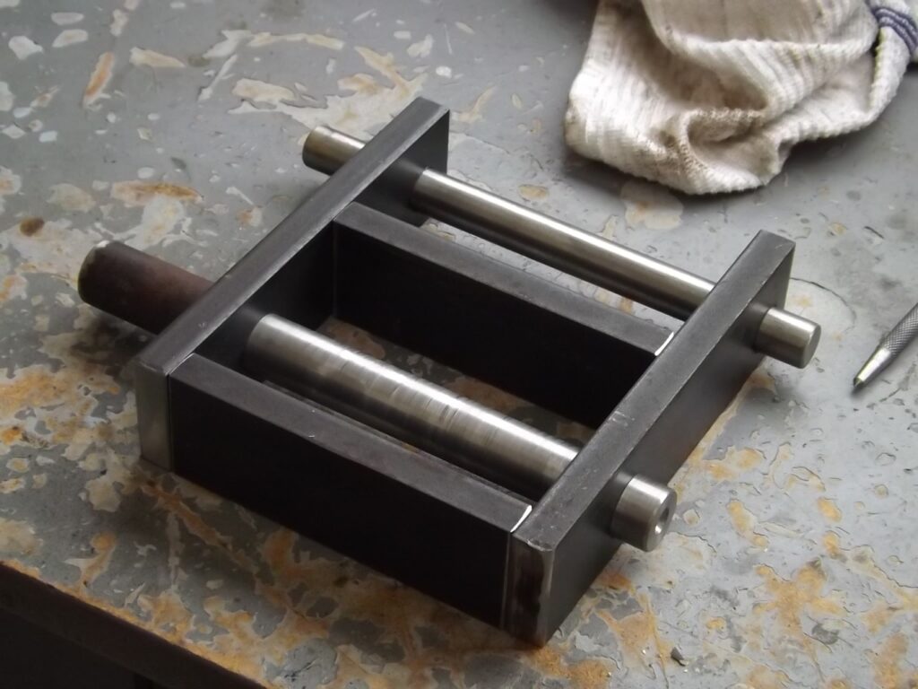
Image (4) shows both sides of that part tack welded together and drilled for the pins.
The tack welding was the perfect way to align the holes in both sides.
(4)
(5)
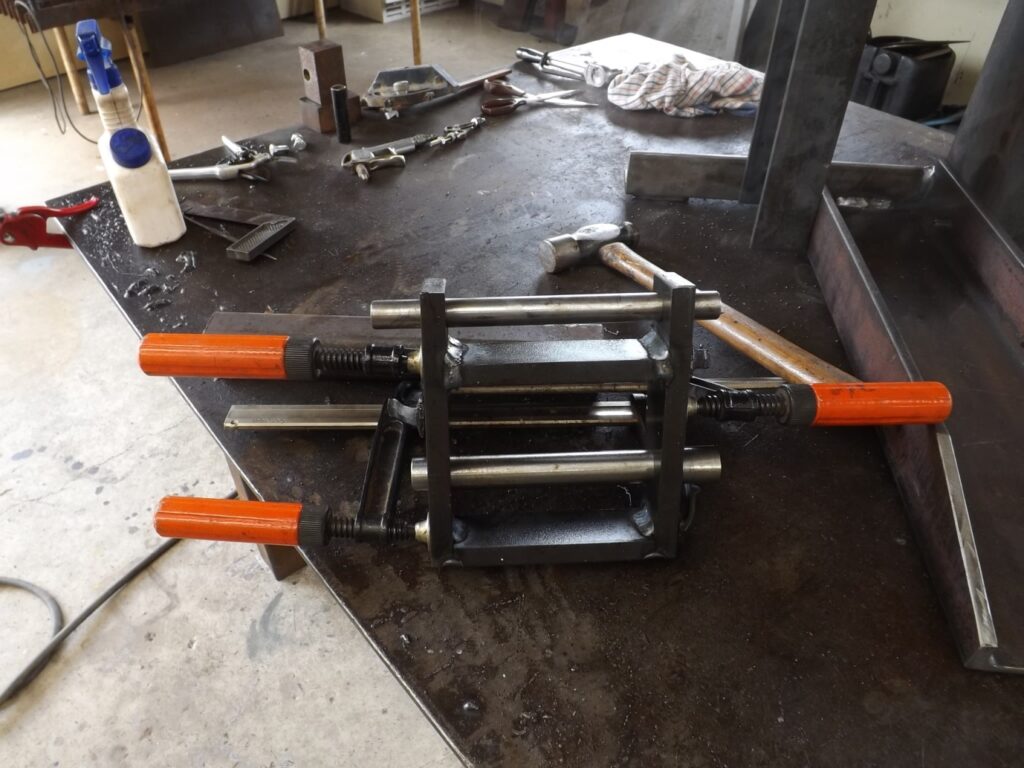
I then made the pins and the end plates for the roller frame and here in
Image (6) they are ready for welding.
(6)
(7)
Image( 7) shows the final plate made up for the bottom roller carrier and ready to be welded in place. The round cut out in it gives clearance for the roller.
The 2 holes are in the plan although you only need one.
The pin in the top of the pressure strut goes through one of them.
I asked Hugh about them and he said he was not sure exactly where the hole should be so erred on the side of caution and put in a choice of two.
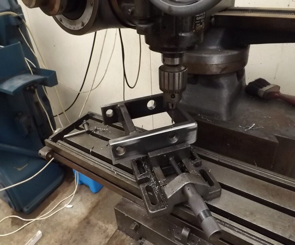
Below in image 8 you see the roller frame in the vice having small holes drilled in the top of the frame in line with the roller pin holes.
They were tapped for countersunk cap screws to retain the bottom roller pin.The pin is flush with the outside of the frame so nothing can protrude To hold the pin in place.
(8)
(9)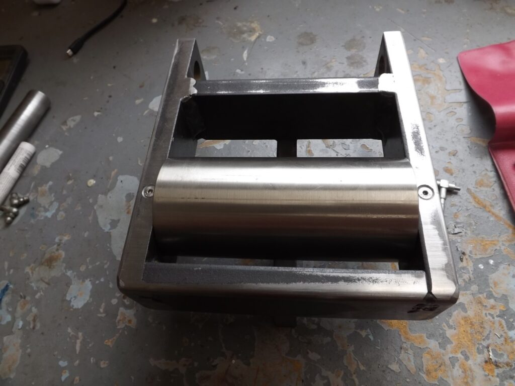
Image 9 above shows the completed roller frame with the roller fitted.
You can see the countersunk capscews holding the main pin in place.
At this stage I should say that I used 63mm stainless roller material.
The plans are for 50mm rollers although that can be changed. One of the mills built had a 50mm drive roller and a 75 mm bottom roller.
I used 63mm stainlaess simply because I had it.
The jury is still out on whether the stainless will wear well but so far it seems ok.
I have drilled the roller and bored it to take the pin right through and stepped it to accommodate a bush on either side for the roller to turn on.
The bushes can run dry but I have drilled the ends of the roller pin on each end so grease can be pumped into each end for the bushes.
(10)
Next I made the camshaft carrier. The initial materials are in the image (10 ) being a piece of angle iron and the three large blocks that are bored to take the camshaft. The carrier sits and is bolted roughly where the angle sits now.
Like the roller carrier sides I have tack welded the steel blocks together to machine them as one.
(11 )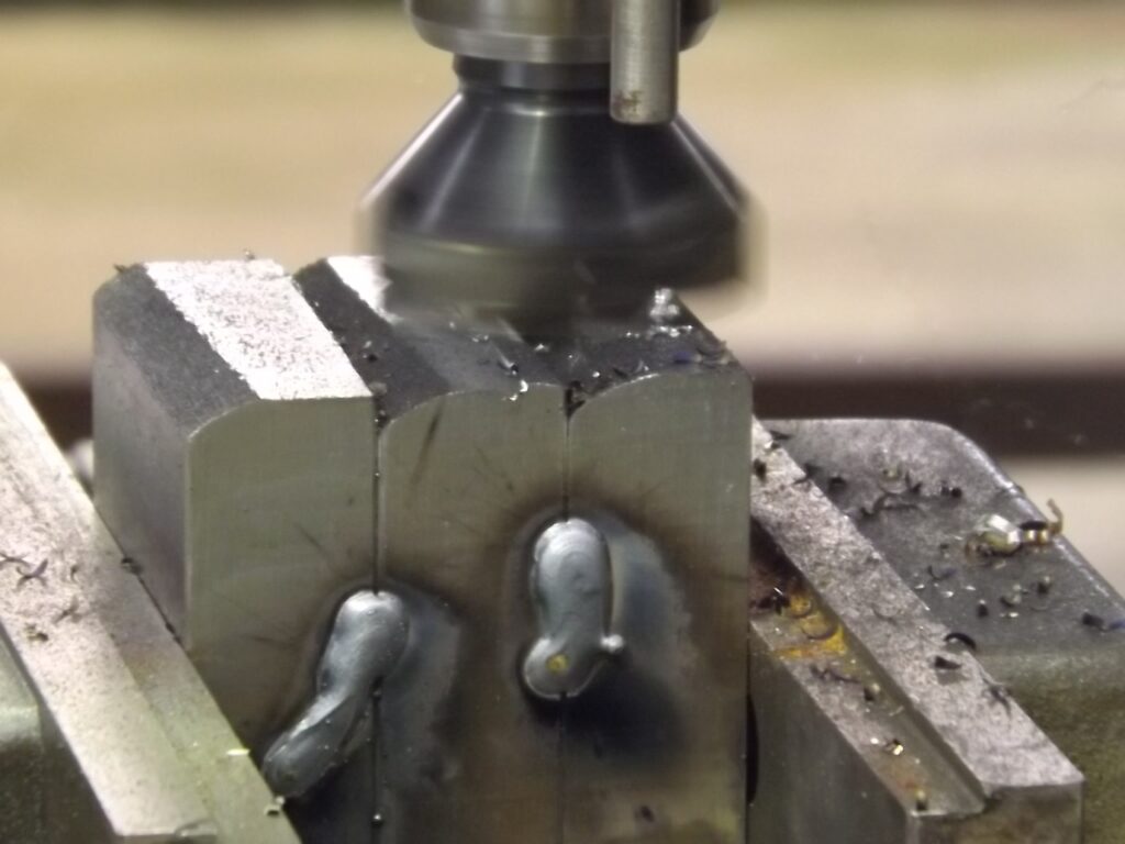
Here in (11 ) you can see them being milled.
( 12 ) Once milled square they are put in the lathe and drilled and bored to take the camshaft.
In order to finish the camshaft carrier the camshaft follower and the camshaft itself must be completed to set up the blocks that have just been bored and help position them to be welded.
( 12 )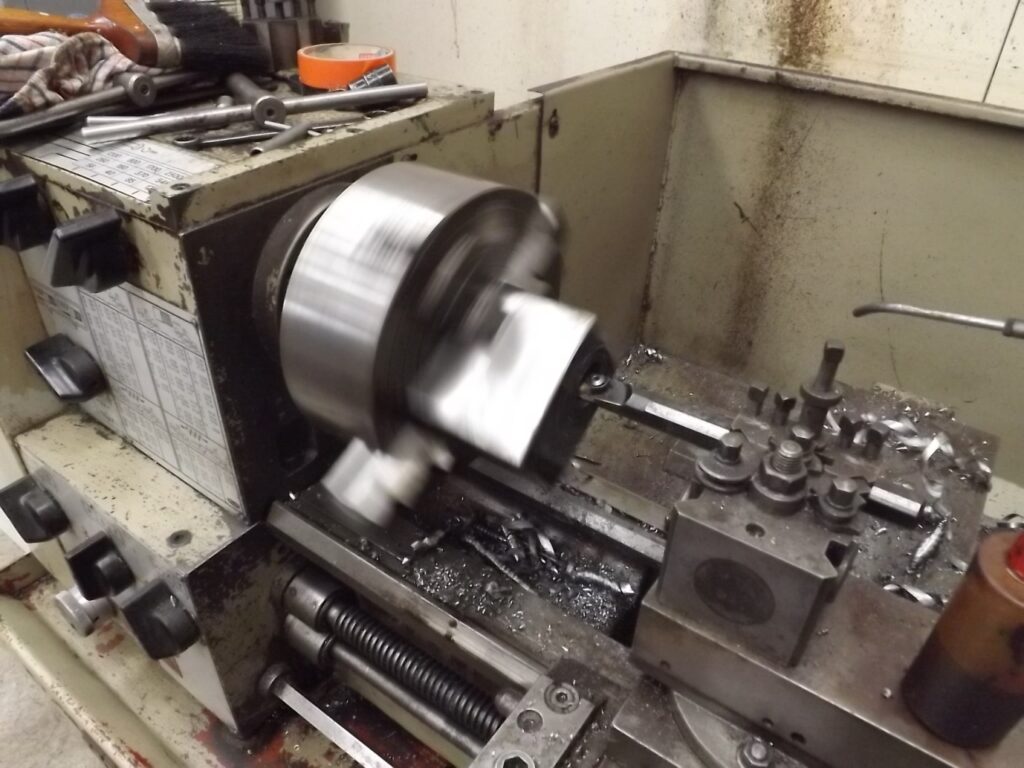
(13 )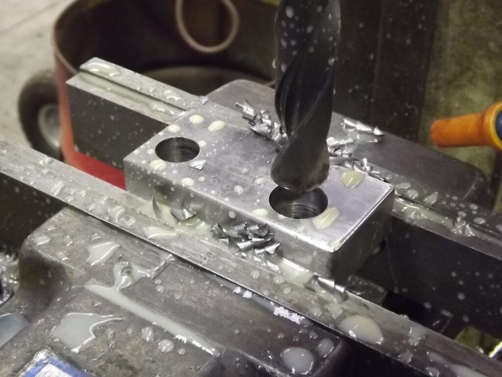
Here in (13 ) you can see the block for the camshaft follower is in the mill being drilled.
The smaller hole is for the pin that attaches the bottom end of the pressure strut to the camshaft follower. The larger hole after drilling is then milled out from the end and is the part that sits on the camshaft as below in (14 )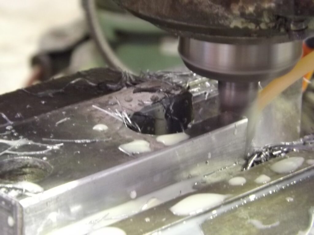
At this stage the camshaft can be made.
There is no harm in making the camshaft a bit longer at both ends as it can be trimmed after the blocks are welded to the camshaft carrier. It is easier to part off a little from each end of it in the lathe afterwards than to find it is short.
The cam itself does not need to be turned at this point.
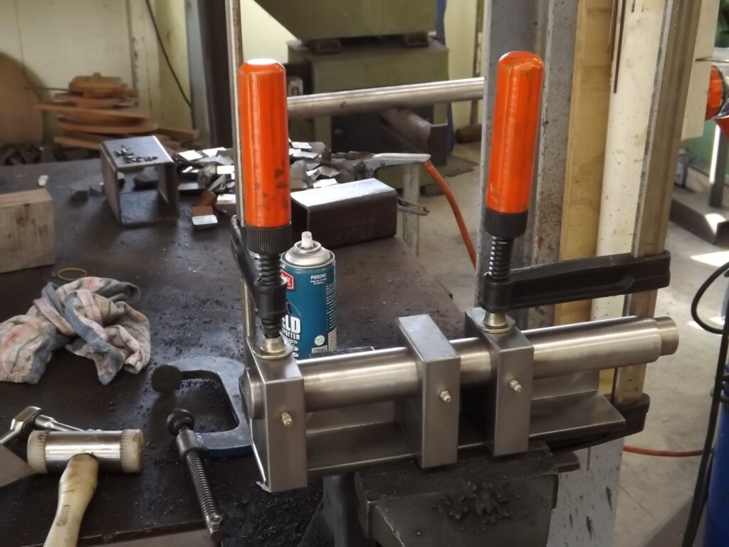
Here in (15)you can see the camshaft, the blocks and the angle for the camshaft carrier all placed together and being clamped in position for welding.
As the welding is done you must keep checking to see that there is free movement in the camshaft. As is normal when welding a piece of this nature the welding will tend to pull the work. It may be nessesary to give a judicious blow with a hammer on one or more of the blocks in order to keep the camshaft free running through out the process. This is why the camshaft ideally needs to be made before welding these blocks in position.
(15)
I have put grease nipples in the blocks as per the plan to lubricate the camshaft.
(16)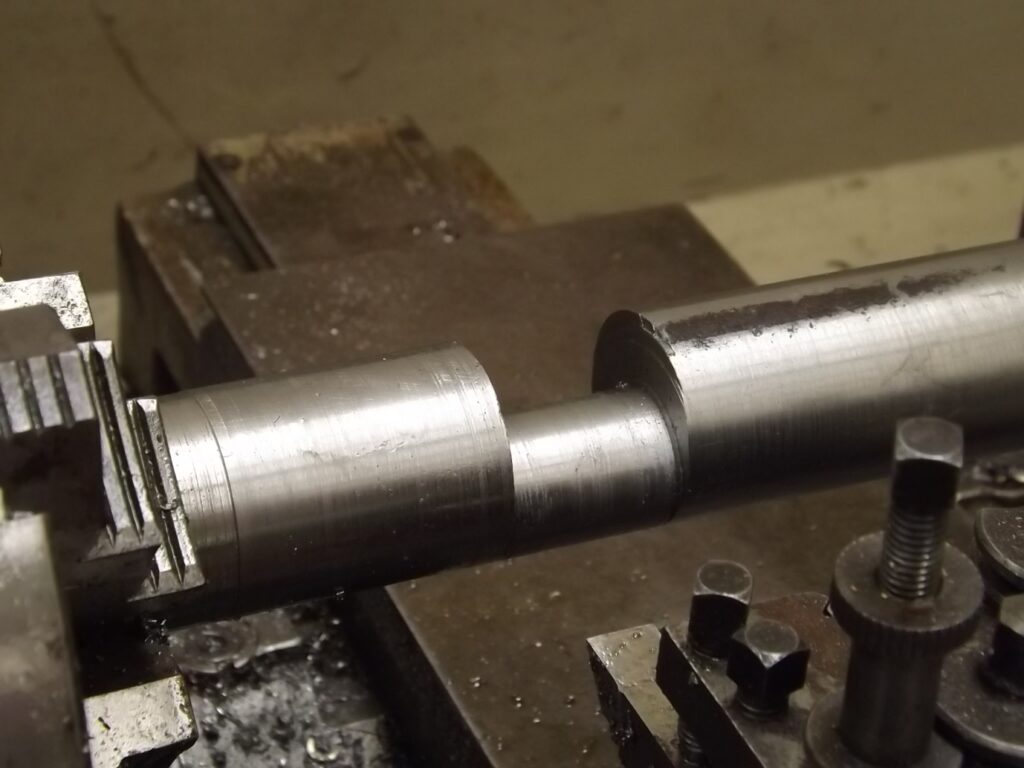
Here is the finished camshaft.
I did this in the 4 jaw chuck but as Hugh said it could be done in a 3 jaw using some piece of metal to offset the workpiece.
