Your cart is currently empty!
Making a Steel Rolling Mill Part 2
We are now back to completing the cam follower.
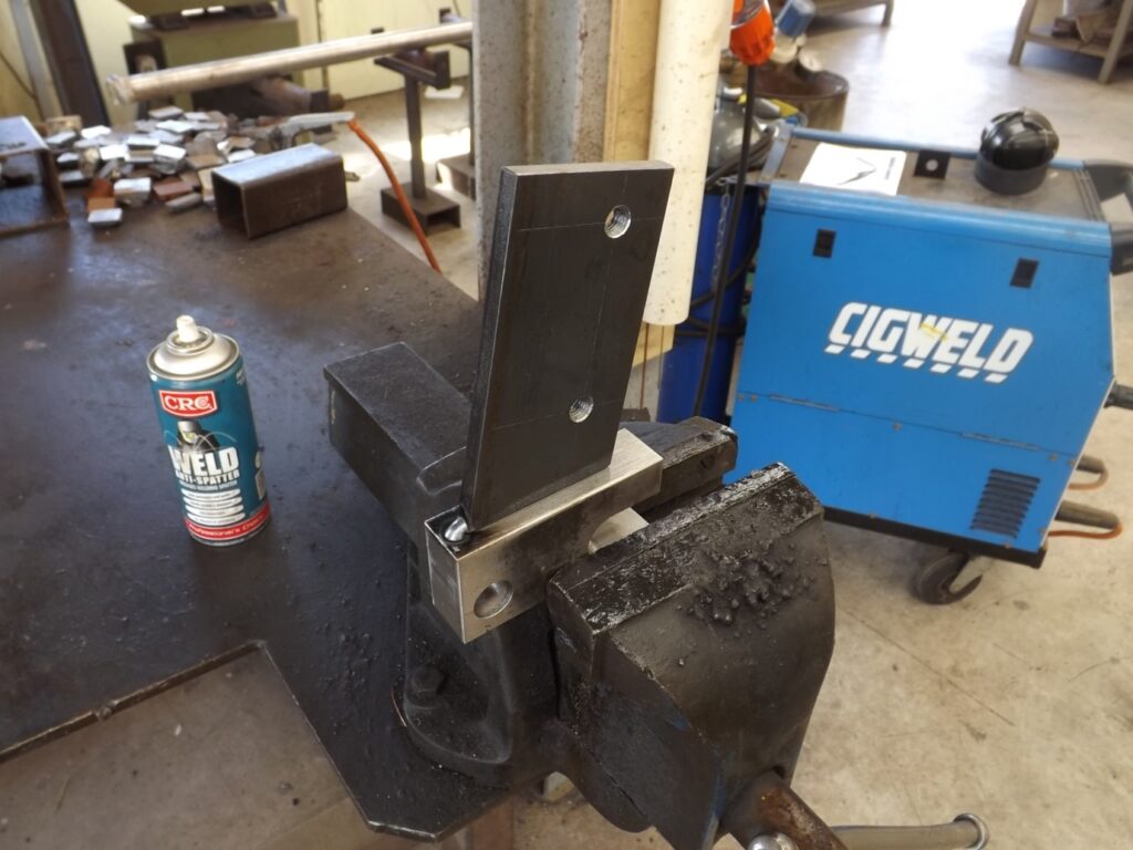
The steel plate that the foot pedal is bolted to is fabricated and welded to the cam follower block that has been milled to sit on the cam itself.
Here in (17) the plate is tack welded to the block ready for the final weld.
(17)
(18)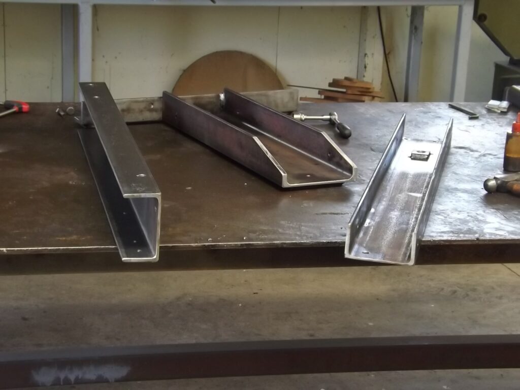
Here in (18) you see the base and the main frame uprights.
The uprights have had further drilling done on them as I have calculated where the holes should go for the bottom roller pivot pin, the main roller bearings and the camshaft carrier.
Below in (19) they have been assembled and the top cap is in place.
There is no top cap in the plans. I chose to make it this way rather than have a welded bar as per plans.
The bearings for the top roller are fitted and the bottom roller frame is in place with its pin.
(19)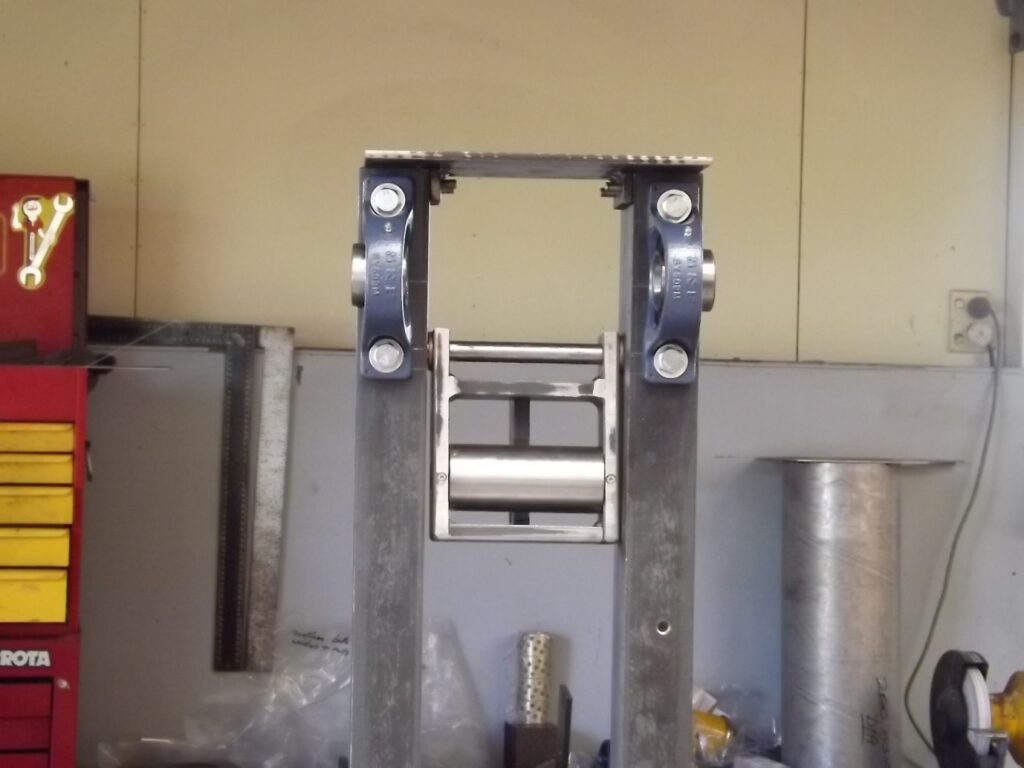
In the plans large bushes are recommended for the top roller bearings.
I fully intended to use this method but decided against it because I found that the edges of the channel that you see the bearings bolted to was not completely square with the main flat of the channel.
I was worried that if I used bushes when I bolted the housings to the channel it would miss-align them and cause the roller to jam.
As a consequence I used the bearings you see there. The good thing about those bearing is the as well as the bearing in the housing being self-aligning the housings themselves have small slots were the bolts go through and this allows enough adjustment to get the correct alignment with the bottom roller.
(20)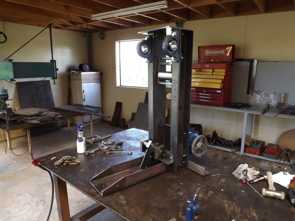
In (20) you see the camshaft carrier in place, the camshaft in it, with the camshaft follower sitting on it
This does just sit there and is held in place by the bottom end of the pressure strut when that is attached.
You will also see the motor installed. I will not bother describing the making of the motor mount. It is simply a flat plate but the placement of the holes and position will depend on the motor and drive components.
(21)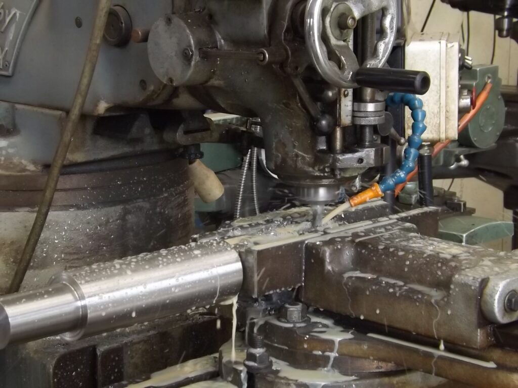
(21) Here is the main driving shaft and top roller that has been turned and is in the mill having the keyway slot being milled for the large drive cog.
Now that the main bearings are in place I have measured the dimensions required to make that shaft.
I have left both ends longer than need be in particular the end that the drive cog goes on as I am not sure at this stage exactly what position that cog will have to sit on the shaft.
The other drive train components will determine its position as it will them.
(22)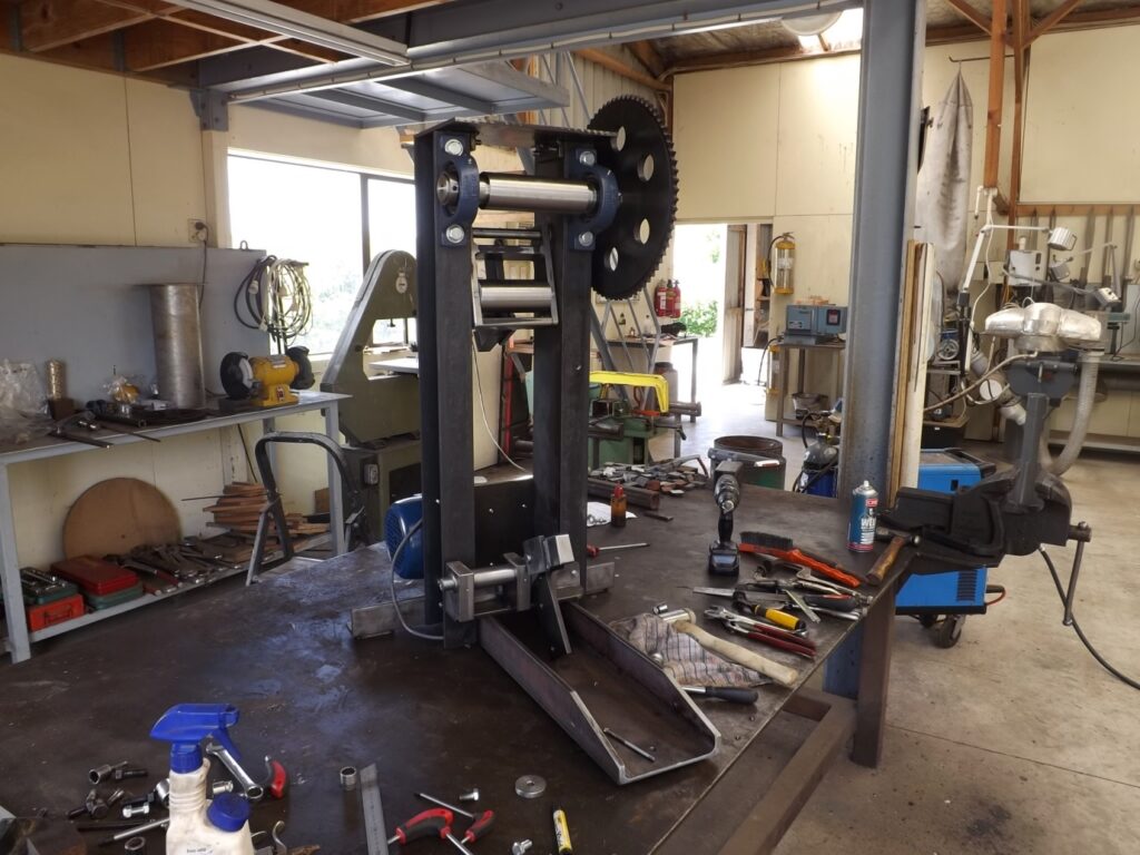
(22) Starting to take shape. Here is the main shaft in place and the main drive cog in place. The cog has 72 teeth.
(23)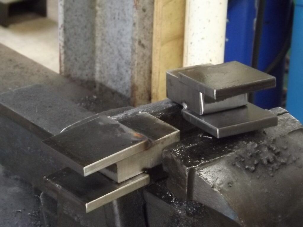
(23) Here are the 2 blocks and side plates that make up the top and bottom ends for the pressure strut.
Here they are being welded and then drilled after welding so the holes align for the pins.
(24)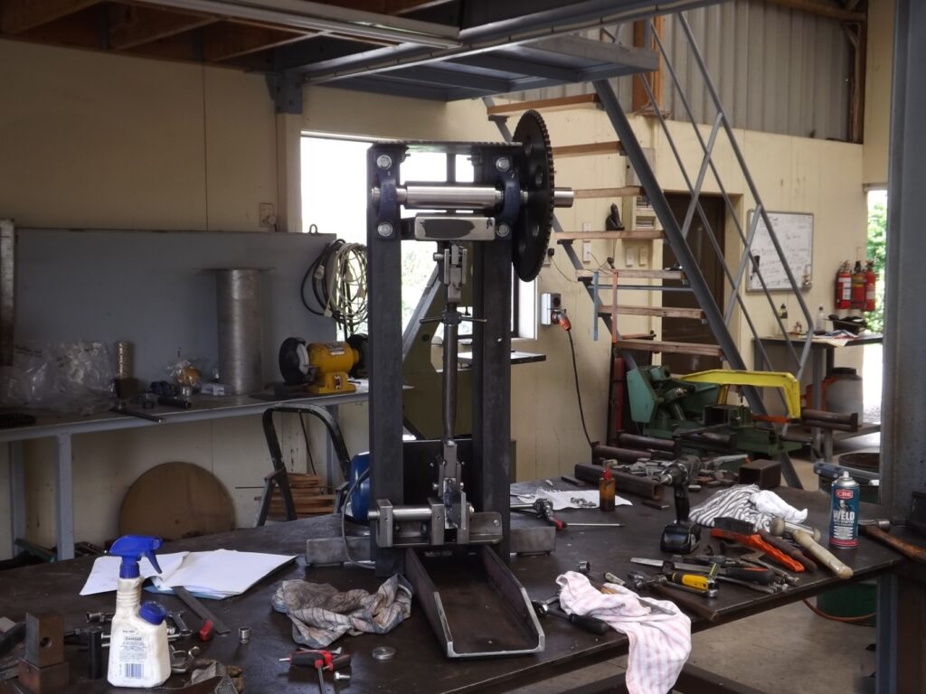
(25) The pressure strut is now in place.
I have not bothered photographing the star wheel construction as it is only a nut with 3 spokes on it ….very simple.
The other components of the pressure strut are assembled here being the pipe and threaded rod.
The threaded rod being welded to the top pressure strut end and the pipe to the bottom pressure strut end. The star wheel in the middle allows for adjustment. The pressure strut is pinned in place at the top and bottom.
To remove the pressure strut at this point it is simply necessary to take out the top pin. The whole pressure strut and cam follower comes away and the pressure strut will part in the middle where the threaded rod goes into the pipe.
(25)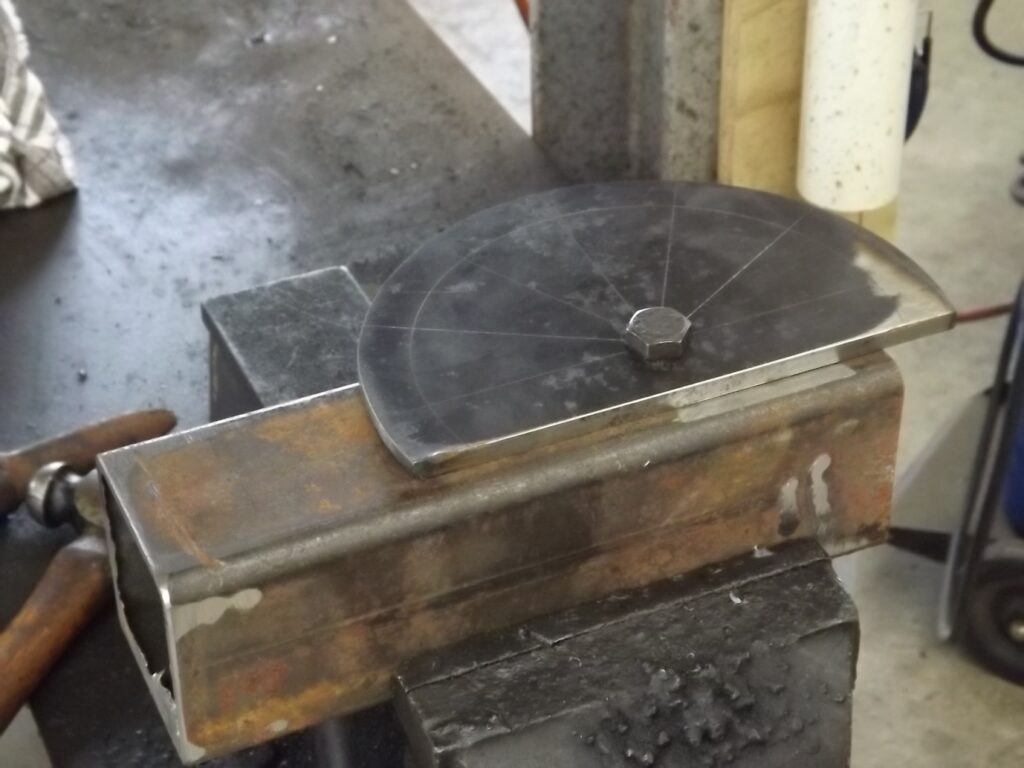
(25) The camshaft lever follower
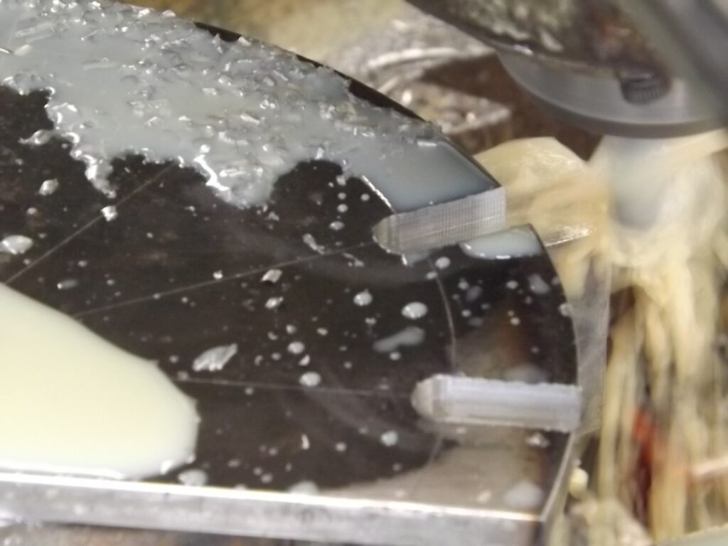
I decided to mill the slots in the follower rather than drilling holes and cutting into them. I did that by mounting the follower on the piece of box section you see there. You can see the lines marked for each slot.
I then put that in the milling vice and made sure the work piece was well locked down.
I then milled each slot to the required depth one increment at a time.
(26)
(27)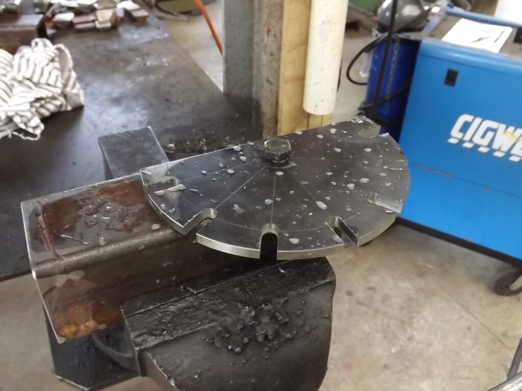
The central hole that was drilled to accommodate the bolt was then drilled out to the required size to go to the end of the camshaft.
(28)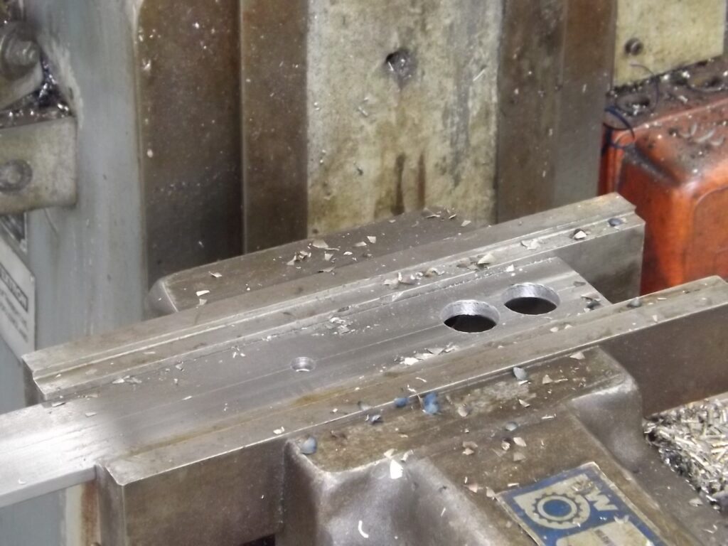
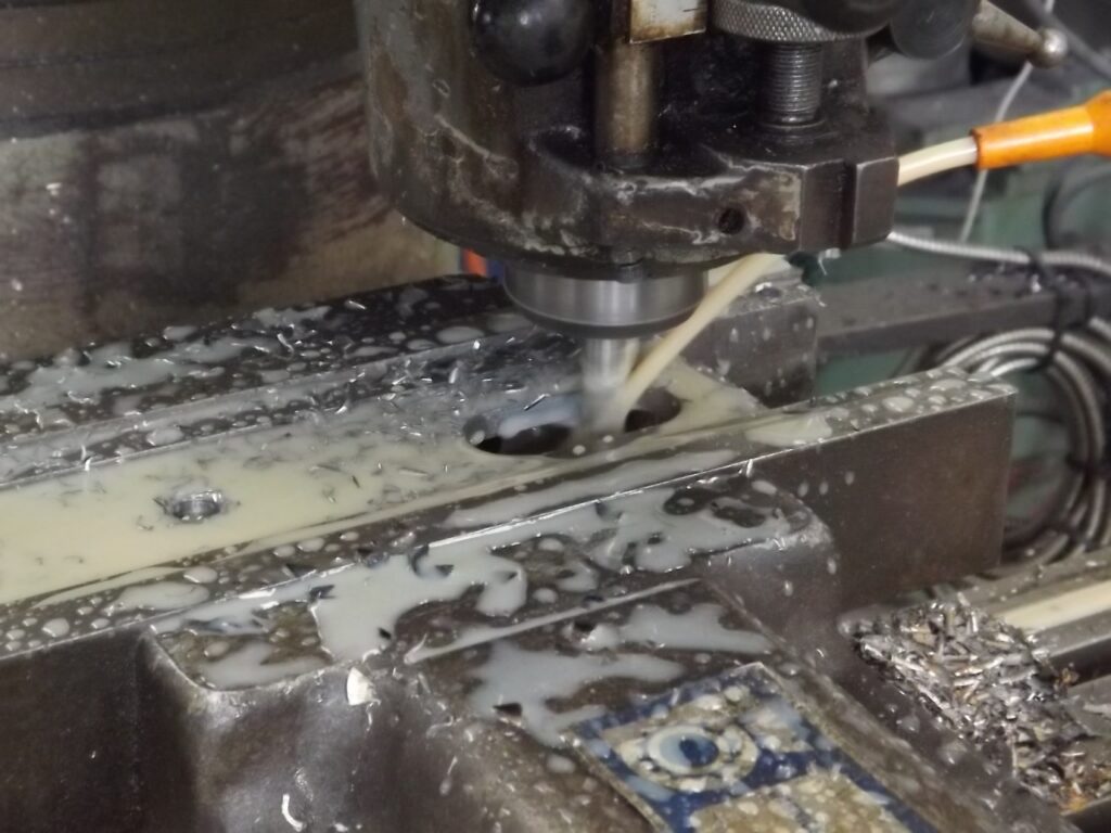
(28 & 29) The side lever plate was started by drilling 2 holes the correct size and milling out the remaining steel.
(29)
(30)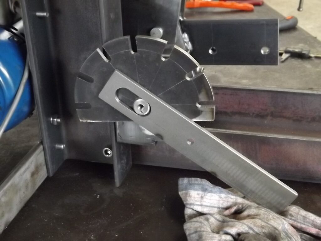
(30) The start of the side lever.
The end of the camshaft has been drilled and tapped to bolt the retainer on for the side lever.
(31)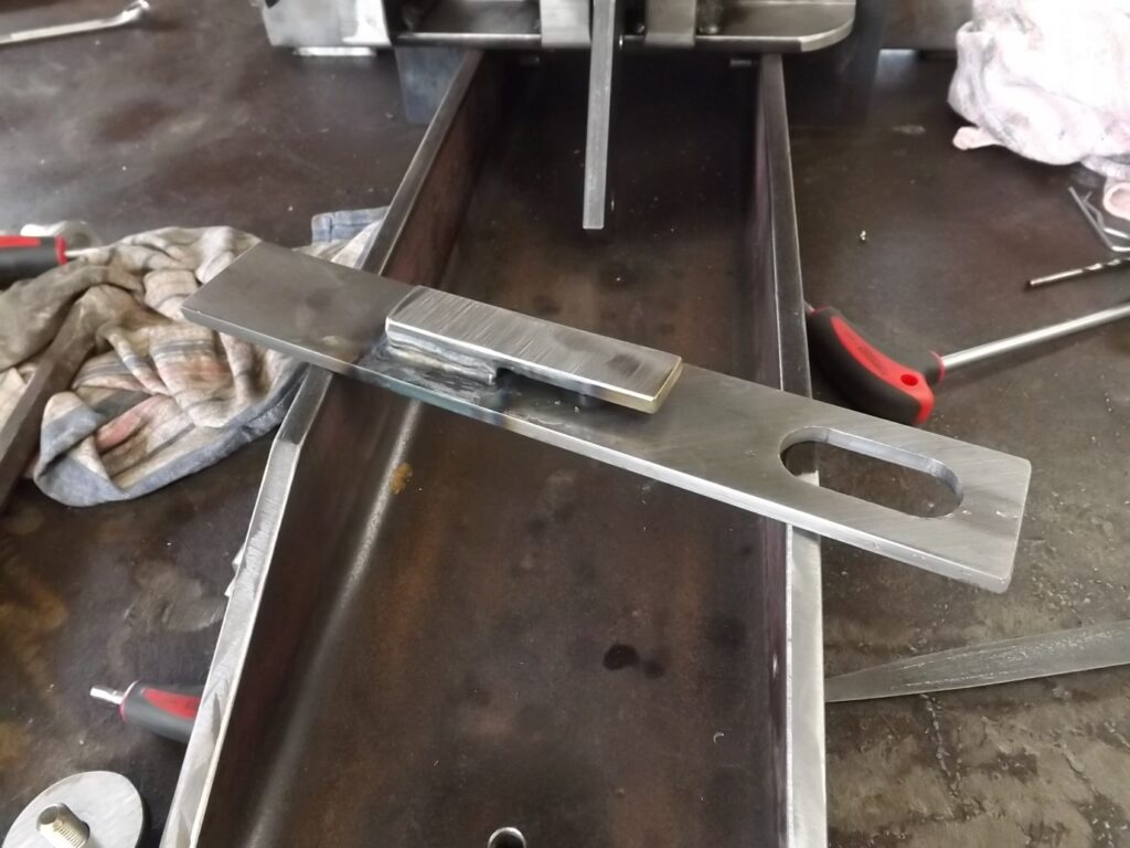
(31) Here is the other side of that plate with the “ clip” and “dowel “ tig welded in place.
(32)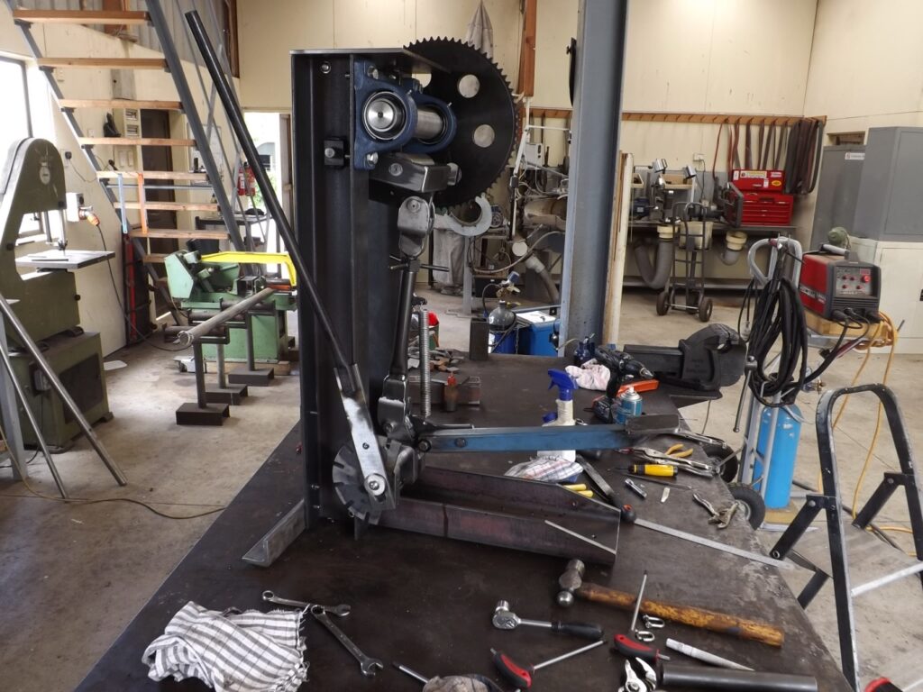
(32) Here is the cam lever sector and the side lever in place.
In this image you will also see the foot pedal in place.
Not much to say about that.
It is very simple, I used box section instead of angle for it as it was available.
I have bolted it to the cam follower.
