Your cart is currently empty!
Making a Steel Rolling Mill Part 3
(33)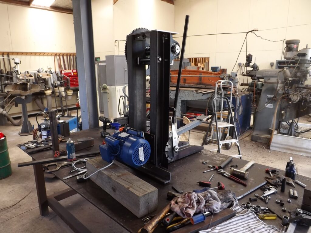
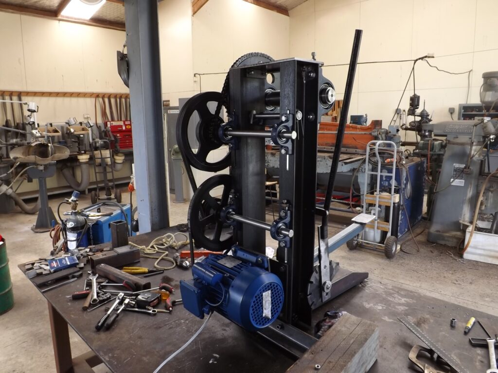
At this stage it is time to start working on the drive train.
My drive train was very similar to the one shown in the plans.
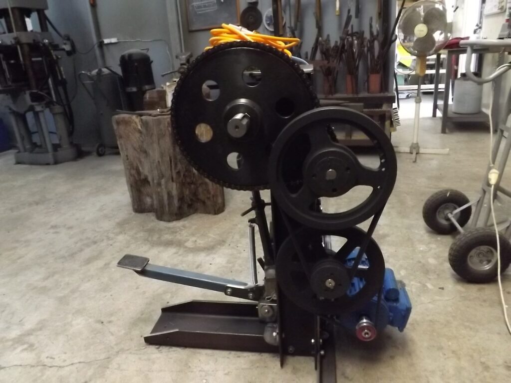
Below in (34) is the completed drive train and helps to show the sequence of components.
It starts with a 3 HP 1400 RPM single phase motor. On that motor is a 57 mm A section pulley.
On the next shaft up is a 300mm A section pulley. The next pulley is a 105 mm double B section on the same shaft. This connects to a 305 mm double B section pulley on the next shaft up.
The next component is a 15 tooth 5/8 th chain sprocket on the same shaft and up to to the 72 tooth final drive sprocket which is on the end of the main drive roller , the shaft and roller being turned as one piece.
(34)
(35)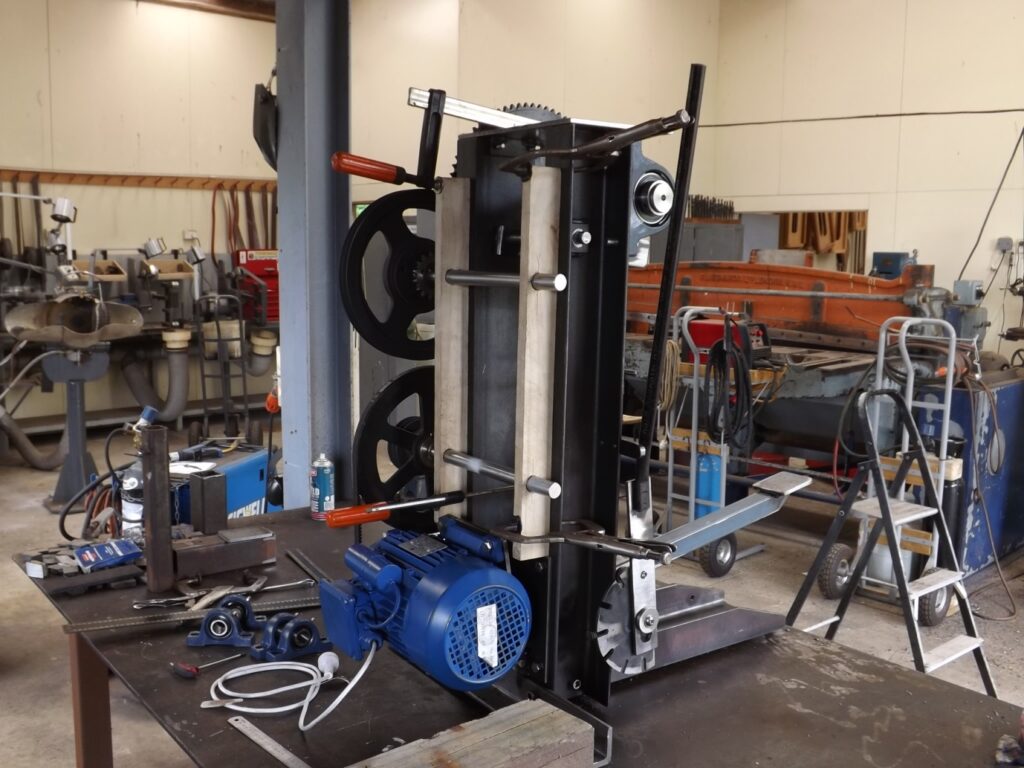
In the image above (35) was my way of setting up the shafts to establish where they would eventually have to be bolted. You will see a couple of pieces of wood, about 75 x 25mm clamped in place. I have drilled them to accommodate the shafts at the same distance out from the main frame uprights that replicated the distance they would be out when in their bearings and housings.
I could move the pieces of wood up or down or re drill them if need be very easily. The drive train components need to be moved about to figure out their final placing without one interfering with the other.
There is no more room than you need to get them in place. I think it is a good idea to leave those shafts a bit longer than needed until finished.
(36)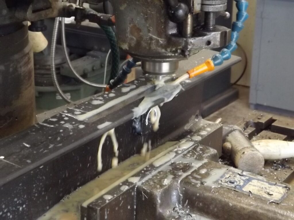
After working out where the bearings had to be bolted on I took the main frame uprights off and milled slots to accept the bolts from the bearing housings. The slots gave me a final bit of adjustment for the shafts when reassembling the mill and for tensioning the belts and chain.
(37)
(38)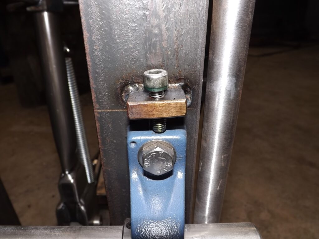
(38) Shows the lug and cap screw I welded above the bearing housing to tension the belts on the shaft just above the motor.
I did not put lugs like these on the top shaft as they were unnecessary.
To tension the drive train I started at the top. The chain was fitted to both sprockets and the shaft and bearing housings tapped lightly so they moved down in the milled slot.
The chain does not need or want to be drum tight therefor as mentioned above there is no need for a tensioning system on that shaft.
With the belts fitted to the next shaft down it could be tensioned using the tensioning lugs in (38)
With the B section belts tensioned the final A section belt can be fitted to the big pulley and motor pulley.
Although I said previously there was not much to the motor mount here is a shot of what I did.
(39)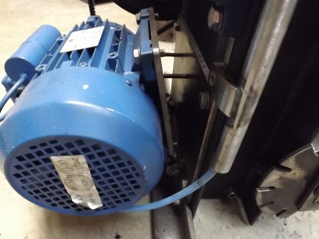
I made a flat pate that mounted on the main frame up rights and from that I had a plate hinging from it that the motor is bolted to. There are 2 bolts pushing the plates apart and supplying the tensioning force.
(40)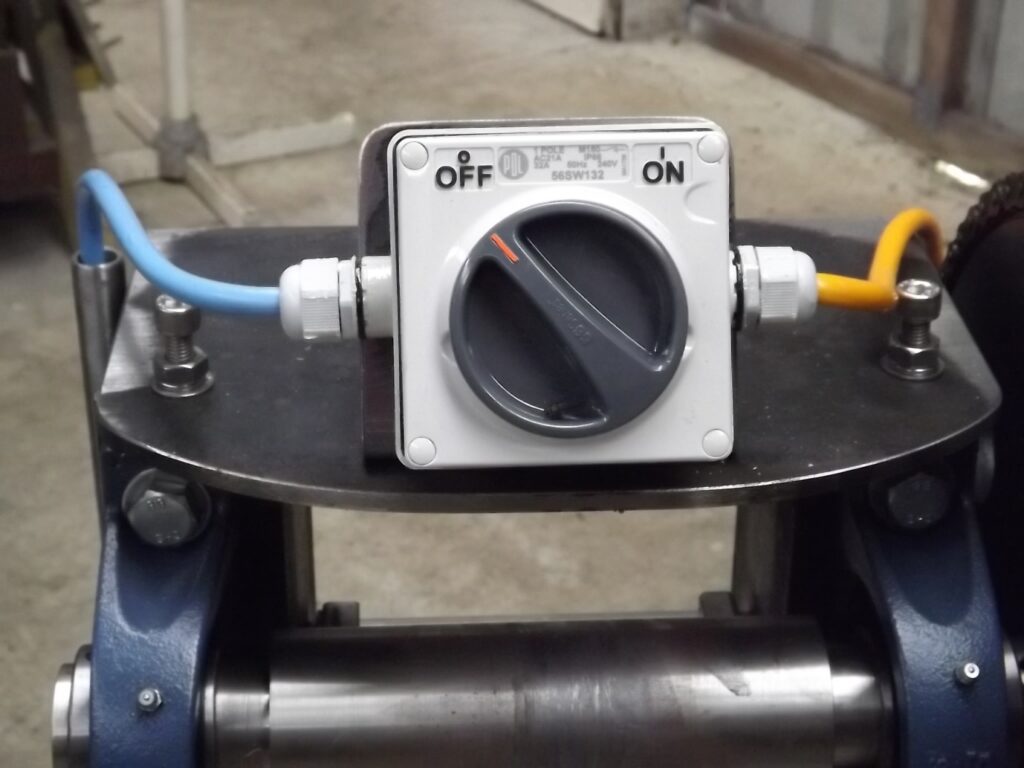
(4) Here is some closer detail of the top cap when finished.
You will see it is use full to mount the switch on. To be fair it is not necessary to have a switch but more convenient that going to a wall switch every time you want to turn it on.
The cap screw adjusters next to the electric cables are to stop the main shaft from lifting from the upward pressure of rolling the steel.
(41)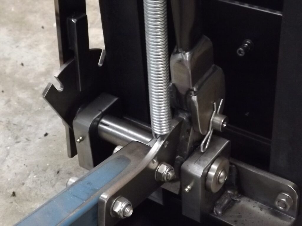
(41) This shot gives a little more detail of the camshaft, cam follower area.
In the plans you will see there is a nut welded to the bottom of the pressure strut just behind where the spring hooks in. Through the nut is a bolt and that is used to limit the upward movement of the foot pedal so when it rises pulled up by the spring it does not push the cam follower and the pressure strut over centre.
I have not included it here as when I assembled my mill the pedal stopped in the right place without it.
I have to admit it was not good planning on my part simply coincidence.
Well that’s it for the build.
The mill is now at the stage that I can use it. I am compiling a list of small changes and things that need to be finished on the mill when it is disassembled for painting.
Before then I will make up gaurds for the drive train and fit them.
I will probably do another section to this document which will be : Making a Steel Rolling Mill Part 4.
This will not be for a few months and then in it I will show the final finishing of the mill and any changes that I have thought of based on my use of the mill.
A Few More Thoughts
The Drive Train : In his instructions Hugh has stated that he considered anything over 1 1/2 horse power for the motor was probably wasting horsepower.
On my mill I have used a 3 hp motor because I had it.
Wether I need more HP on mine because the main roller is 63mm in stead of 50mm on the other mills in the plans I DO NOT KNOW.
I would given the choice use a 900 rpm motor rather than the 1400 rpm that I had as that would decrease the size of the other drive train components required. I mention it because if you are buying a motor it would be worth considering.
The two biggest factors that will effect the speed of the roller is the speed of the motor and the size of the pulley on the motor.
It is worth trying to buy the bigger pulleys and cog cheaper from an auction site and then buying the smaller ones from a supplier to give the required speed.
The speed that the rolling mill does in the plans is 10 feet per minute. Mine to start with in spite of calculations was 17 feet per minute.
This was too fast to my mind and I slowed it down by turning down the diameter of the pulley on the motor. It is now doing 12 feet per minute and that seems good.
Roller Height Adjustment: There are 3 ways to change the height of the rollers or should I say the gap between them.
The foot pedal. The obvious way, this will lift the bottom roller when stepped on by applying force through the cam follower and pressure strut.
The star nut. This when turned clockwise will lift the roller by changing the length of the threaded rod.
The Side Lever. This seems to be a very misunderstood part of the mill. I have seen comments on the net by people who say they do not use the lever (on their own mill) or suggest to people building a mill to leave it off as it will save building time. I have no doubt it will save time in building but will also do away with one of the finer points of the mill.
The idea is that once the star nut is adjusted and you have taken the first roll on the hot steel through the mill, you can by pulling back on the lever get ( on average ) another 2 bites on the work in the same heat.It is the fastest means of raising the bottom roller and making the best use of the heat in the steel.
There is no way that turning the star wheel or using a hydraulic jack as some mills have is as efficient or effective.
